
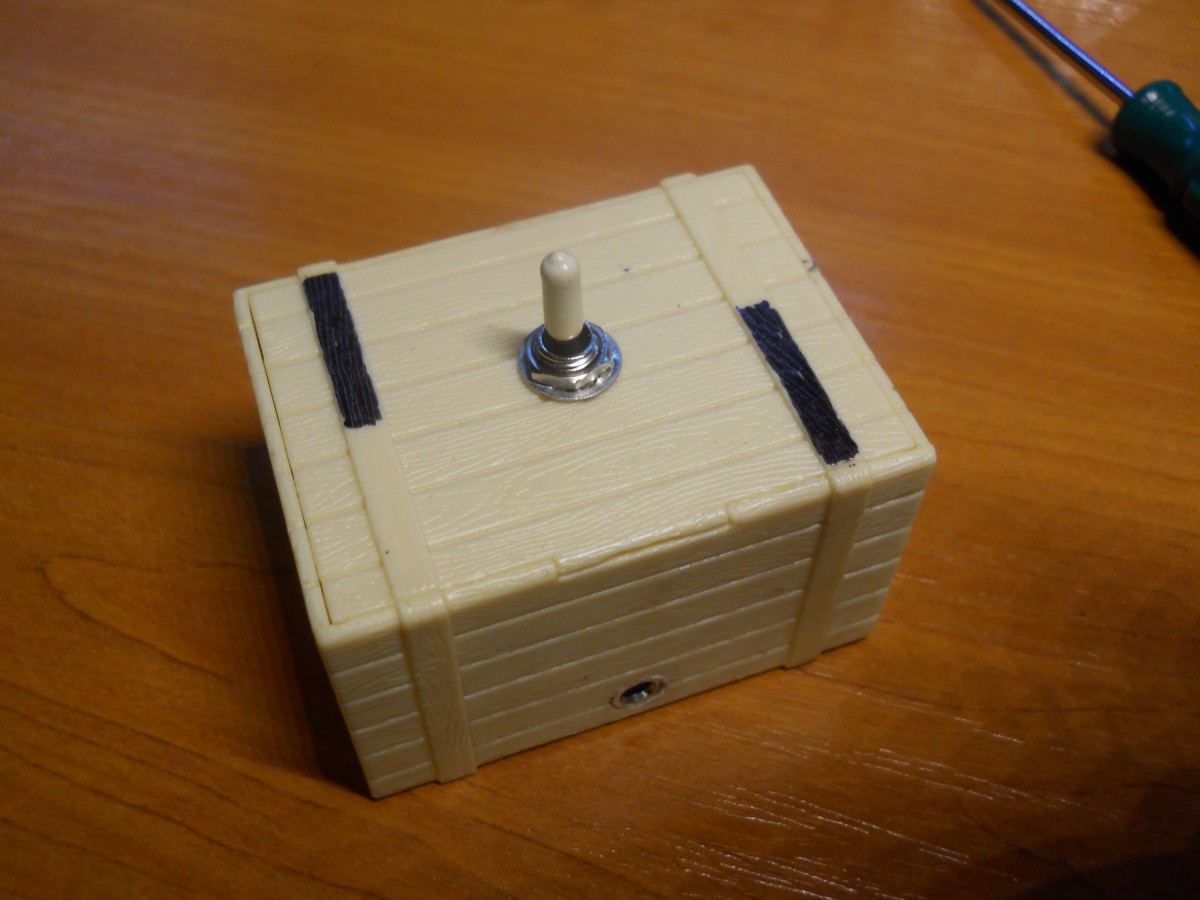
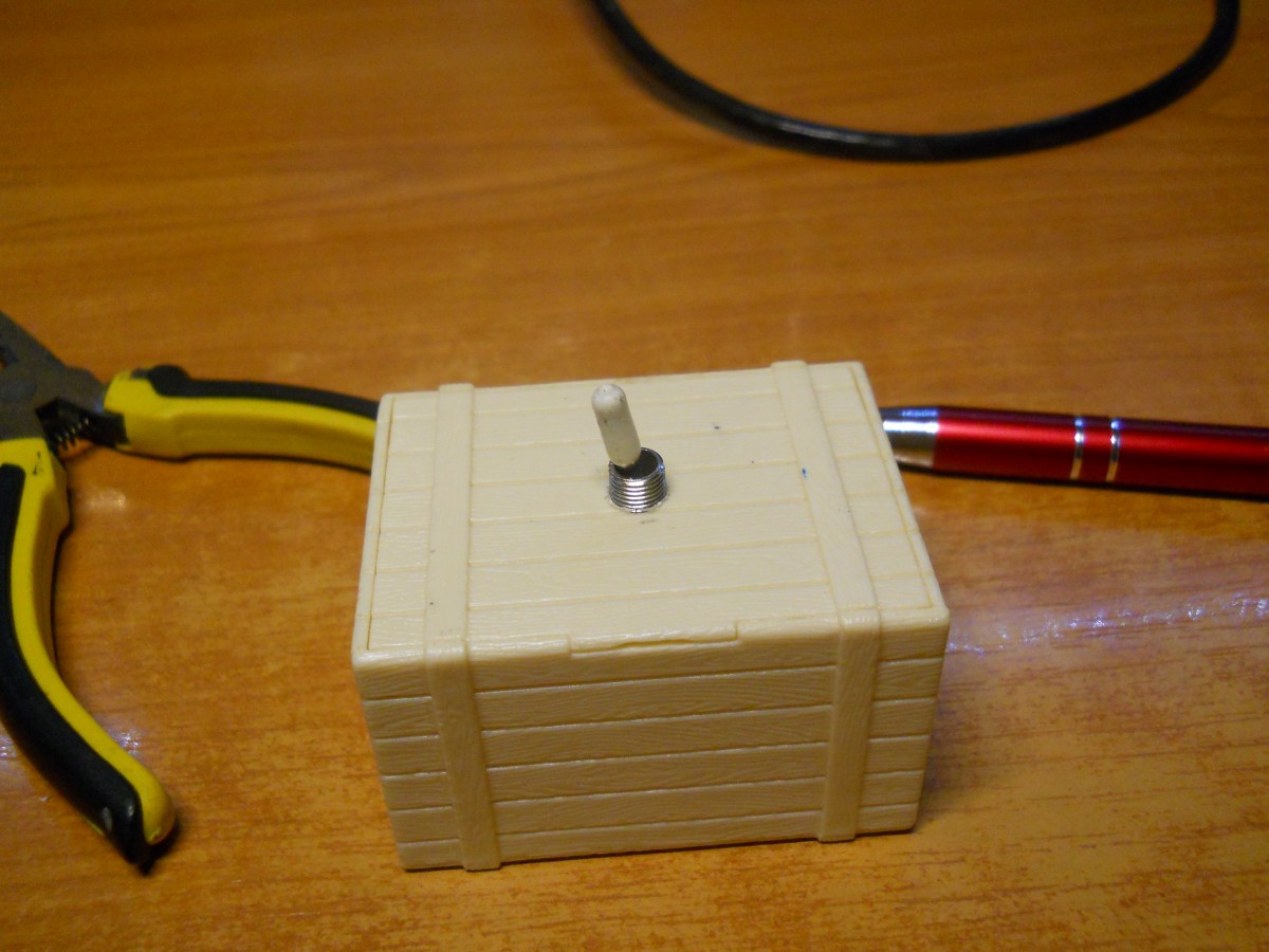
So, since I got an old audio station on my desk, I wanted to be able to connect both the desk PC and another device (phone, laptop etc.) to the station without too much hassle. The best way to do this was a 3.5 mm audio switcher. Since after searching online I came up empty handed I decided to build one myself. This is the final result:
Parts used:
- Old toy plastic box
- 2 pole 3 way switch
- 3 x 3.5 mm female stereo jacks
- some colored wires
Tools used:
- Electric screwdriver and bit
- Easy PDA
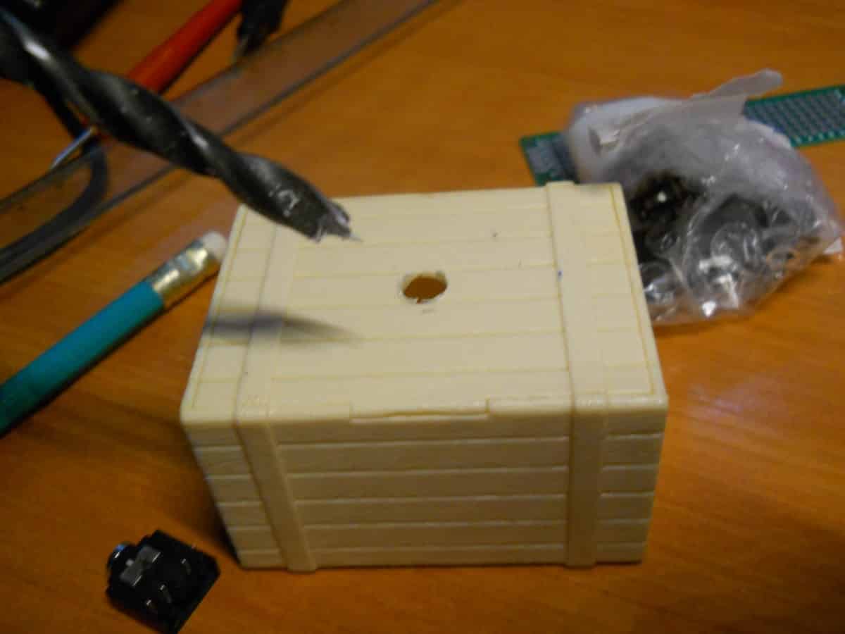
1. Preparing the plastic box
First up, I had to come up with a way to mount everything inside the box. I decided to do this before doing any soldering, just to make sure everything worked. To this end, I used an electric screwdriver with a bit the same size as my switch. Fortunately, the bit was also perfect for the 3.5 mm jack holes.
2. Connections
So, now satisfied that everything fitted in the box, I needed to make all the required connections. To this end I used Easy PDA, an online tool that lets you easily create sketches and PCB layouts (not needed for this project).
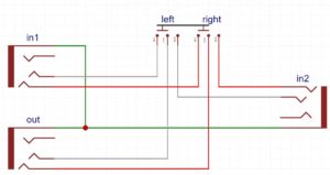
The unconnected pins are used to determine if a jack is inserted or not, which was not necessary for our build.
Next up, I had to solder everything together. The jacks were a bit of a pain, as the plastic around the connection pins melted sometimes while I was soldering, but eventually I got everything connected.
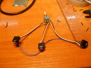
I also took this opportunity to do a quick check, just to make sure everything worked. First using a multimeter to check for shorts, then plugging it into the station and testing it with my phone.
3. Putting it all together
So, now with everything connected, I just had to put it all in the box and fit the jacks and switch through their respective holes.
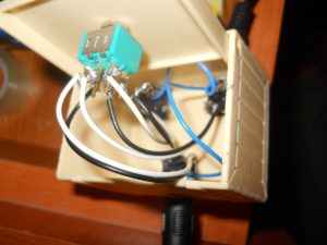
I also did another check now, just to make sure. But quickly, I realized I had a problem. The jacks were very easy pushed inside. I thought I could solve this with glue but I was wrong. So, what to do? Lego to the rescue!
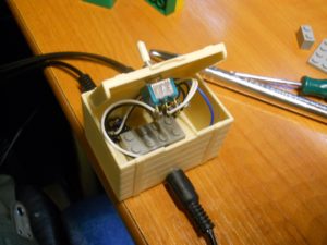
A lego brick was the perfect width and length to keep everything stable. It was a tight fit, but that was very good in this case.
4. Final touches
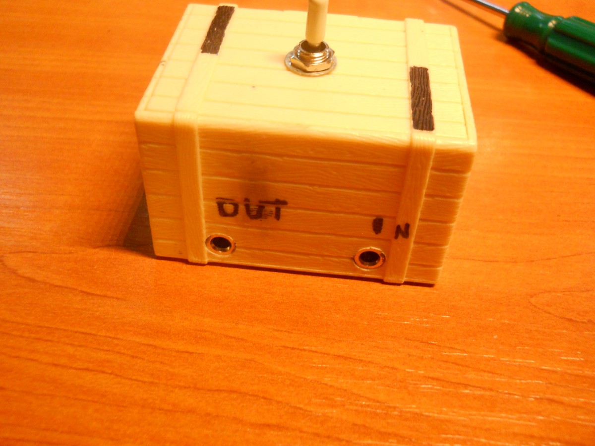
As a final touch, I marked the Output and Input on the back, and added some black marker lines to indicate which input the switch was connected to. In the end it looked better than expected.
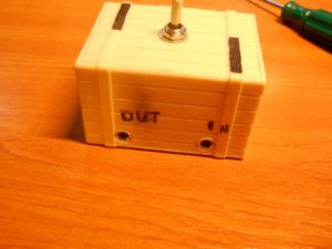
Using some double tape, I fixed it on my desk, where it has been doing its job for the pas few months.